top of page

Part & Assembly Drawings Title Page 1

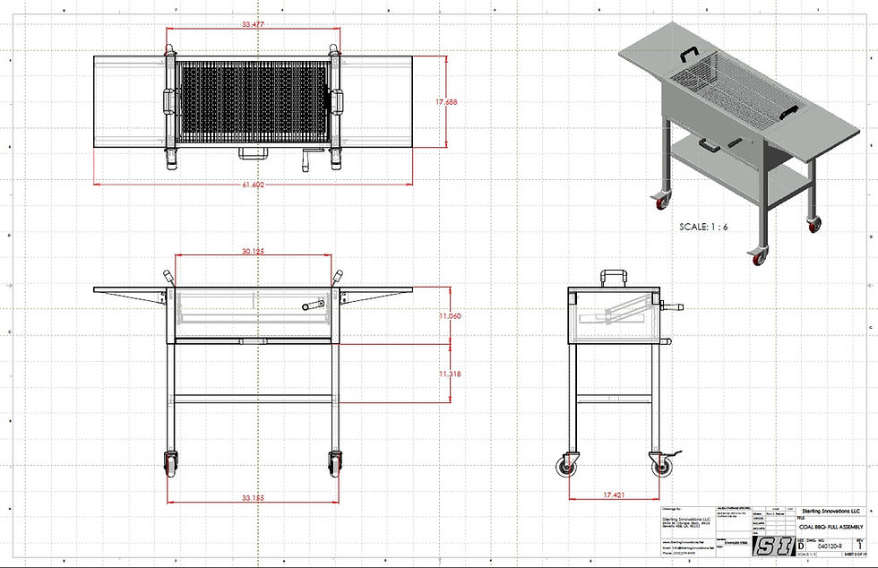
Coal BBQ P3

Sign Holder Flat 4

Part & Assembly Drawings Title Page 1
1/7
PART & ASSEMBLY DRAWINGS
Sterling Innovations is well experienced at creating all sorts of technical documents such as: CAD drawings, “spec sheets”, catalog pages, installation sheets, assembly instructions, 3D Models, Manufacturing Drawings, photometric-analysis-based product performance comparisons, and more.
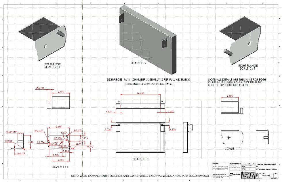
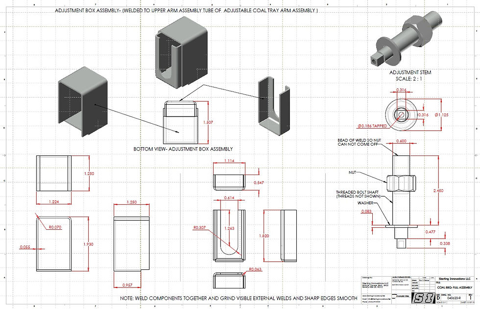
Ideal plans for designing, reverse engineering, manufacturing, constructing, and building a product or assembly, should include a combination of individual dimensioned part drawings, part and component locations within the assembly, individual part identification call-outs and counts (BOM), construction information, virtual 3D models, and more.
Having detailed drawings of products is important for several purposes, including:
● Designing new and refining existing products
● Sourcing new/alternate factories to build your custom parts and assemblies
● Using an existing product's construction concepts as a guide in forming the basis for a new off-shoot or a variation on the existing product
● Organizing the component parts and creating a BOM (bill of material) to pin down and list all of the parts and the details which comprise each assembly
● As product assembly and/or maintenance instructions for your assemblers or customers
● Products can more easily be controlled, refined, and improved upon with good documentation drawings and version control
● An assurance that should key individuals leave your employ that your product construction details and refinements will not be lost
● Copies, based on similar 3D models, can also be reapplied for additional purposes, such as catalog/cut sheets, UL/ETL listings, installation instructions, shop drawings, manufacturing templates, and more
● Accurate parts drawings can be used as a basis for programming CNC manufacturing equipment or 3D printers for part manufacturing

BBQ Cover Sheet

BBQ P1

BBQ P1B

BBQ P2

BBQ P3

BBQ P4

BBQ P5

BBQ P6

BBQ P7

BBQ P8

BBQ P9

BBQ P10

BBQ P11

BBQ P12

BBQ P13

BBQ P14

BBQ P15

BBQ P16

BBQ P17

BBQ P18
bottom of page
